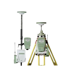
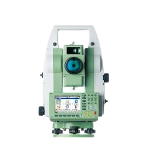
Our Services
Tel: +27 (11) 472 1527
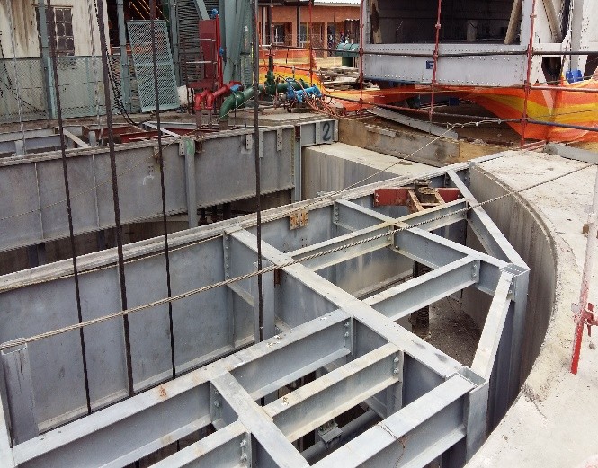
Shaft Sinking & Equipping
Procedures:
- Box Cut Preparation
- Bank Steel Installation
- Head Gear Installation
- Steady & Tape Bracket Installation
- Curb Ring Alignment (Shaft lining)
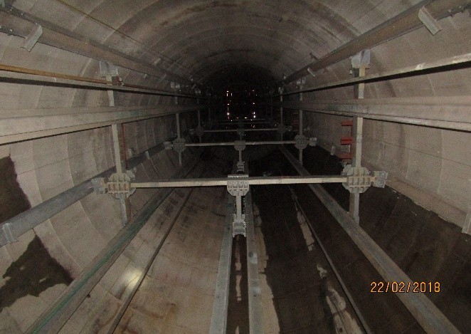
- Equipping of Vertical Shaft (Bunton’s & Guides)


3D Laser Scanning
Accidents Scenes
Vertical Shafts
Underground Tunneling
Steel Structures for Design Purposes
Volumetric Scans
Engineering Scans
Facilities Management
3D Design
Figure 1 – Identification of Geological Structures.
Figure 2 – Ore Pass after shotcrete.
Figure 3 – Cross Section to determine shotcrete variances.
Figure 4 – Vertical Long Section indicating shaft deterioration.
Figure 5 – Cross sections with Plan vs Actual comparison for shaft configuration.
Figure 6 – Plan vs actual comparison of underground development.

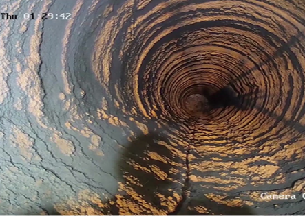


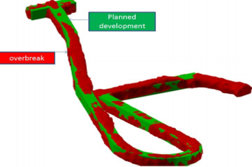
Figure 1 – Point Cloud scan of building.
Figure 2 – Rendered drawing from point cloud data.
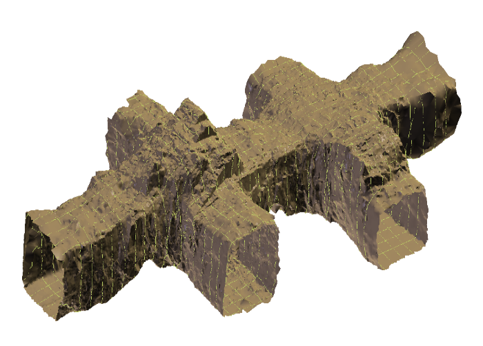
Figure 3 – Underground tunnel & cut away.
Figure 4 – Wire mesh of underground tip area
Figure 5 – Engineering Scan & modelling




Open Cast Mining
1 – Greenfields Area (Before any work commenced)
2 – Ground Control Points for Survey
3 – OGL Contours (Original Ground Level)
4 – ITH (First topsoil removal survey)
5 – Comparison (OGL vs ITH)


GPS Survey
text here
Volumetric Survey
text here
Arial Survey
text here
Construction Survey
text here
Engineering Survey
text here
Gyroscopic Survey
text here
Raise bore Alignment
text here
